Electronic ISSN 2287-0237
One of the wonders of creation in humans is symmetry as this symmetry brings about balance and beauty. The human spinal cord, as the axis of this symmetry, has its own defining principles and curvature. The spinal cord is vital in withstanding body weight and focused pressure, as well as maintaining the nervous system and performing different body movements.
One of the consequences of modern life is the appearance of conditional disorders and pain in musculoskeletal structures especially in young people. These disorders are caused by several factors such as motion poverty, muscle imbalances, individual physical characteristics, physical maturity especially rapid bone growth, nutrition disorders especially vitamin D deficiency, long periods of sitting, inappropriate ways of carrying bags, improper motion patterns, psychological characteristics and also congenital factors. These problems cause illnesses such as kyphosis, which is as a uniform arch on the top of spinal cord, and musculoskeletal disorders, such as scoliosis, which may appear as a unilateral deviation (C-form deviation) or as a bilateral deviation (S-form deviation) of the spinal cord.1
The International Scientific Society on Scoliosis Orthopedic and Rehabilitation Treatment (SOSORT) recommends the following treatments based on the Cobb angle. However, individual treatment may vary depending on speed of progression and remaining skeletal growth (< 20°: Observation, 20°-25°: Observation or brace, 26°- 45°: Brace, 46°- 50°: Brace or surgery, > 50°: Surgery).2,3
Surgery is used to treat patients with high degrees of scoliosis4-6 and these surgeries have several models. Furthermore, day by day with the advancement of science, new models and instruments in the field of surgery for this type of disease are being invented and produced7. For patients with a lower scoliosis angle, regular practice of gestures and exercises, prescribed by physicians and physiotherapists, can be taught to treat patients with these movements alone.8 For patients with severe scoliosis (between 26° to 50°), normally a brace is prescribed. Braces have different types and models, and the famous brands that are prescribed for the treatment of scoliosis, are brace Milwaukee and brace Boston. These braces are prescribed by physicians to patients and by wearing them, after a while, the structure and shape of the spinal cord are reversed.9-11
Today, researchers are reviewing a variety of brace models so that, by designing and analyzing a variety of braces, they are planning to present the best and most recent models for scoliosis patients.12-14
This study has been designed to simulate and compare braces composed of three different materials to determine the optimal material. In this research we will examine the stresses and strains and rate of displacement in the brace, and we will present the results of the analysis.
2.1. Finite element modelling
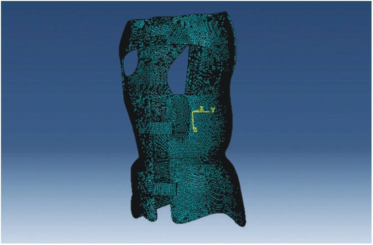
Solidworks and Abaqus software have been used in this study. We redesigned an ART brace in Solidworks software (Figure1, 2) and then after redesigning the brace we entered it in Abaqus to analyze it.15
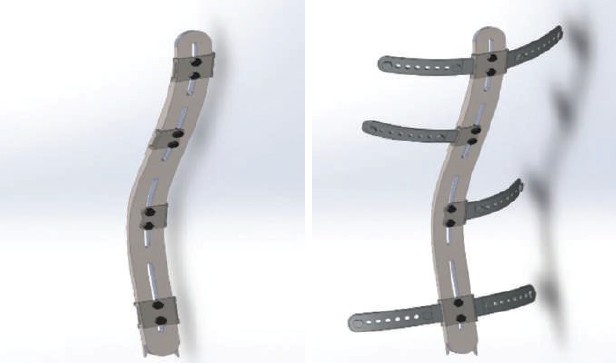
Figure 1: Designing brace aluminum brace in Solidworks software
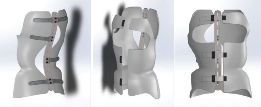
Figure 2: Assembling the designed brace in Solidworks software
2.2. Boundary condition, load application and analysis
In order to achieve the best kind of polymer for this brace we aimed to investigate three kinds of polymer in this research, Nylon 66 with 50% Mica, Nylon 66 with 30% carbon and Nylon 6 with Nylon 6 with 30% carbon.16-18 Table 1 below describes the behavior of these polymers. Additionally, in carrying out the design and analysis steps of this brace, the middle bar of the brace made of aluminum is considered with an elastic modulus of 70 GPa and Poisson’s ratio of 0.3. All analyses are linear elastic and forces on the brace are statistical, see Table 2 below.19
2.3. Meshing
We chose tetrahedron elements with the code of C3D4: 4-node linear tetrahedron to mesh the model (Figure 3) due to the asymmetrical geometry of the observed bodies.
Table 1: Materials behavior
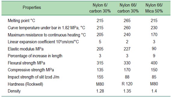
Table 2: Forces on the brace19
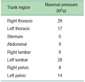
Figure 3: Meshing in designed brace
3.1. Stress Survey
The results reached after having performed the analyses using Abaqus software are as follows in Figures 4, 5, and 6 showing forces on the brace examined in three different materials. The comparison chart of the maximum created stress in braces composed of three different materials is as follows in Figure 7.
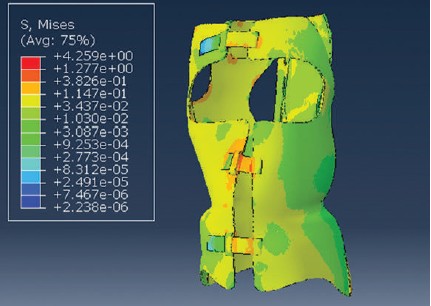
Figure 4: Stress on the polymer brace Nylon 6-30% carbon
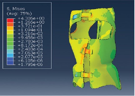
Figure 5: Stress on the polymer brace Nylon 66-30% carbon
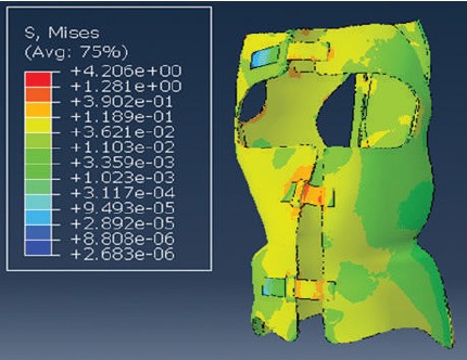
Figure 6: Stress on the polymer brace Nylon 66-50% Mica
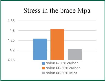
Figure 7: Comparison chart of maximum created stress in the brace
3.2. Strain Survey
According to conducted analysis, the maximum stress is found in Nylon 66 with 30% carbon which has the highest stress, and in Nylon 66 with 50% Mica has the lowest stress. After checking the stress on the brace, we reviewed and analyzed the strain as shown in Figures 8, 9, and 10. Comparison chart of maximum created strain in the brace is as follows in Figure 11.
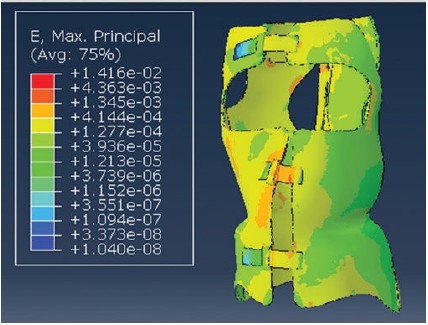
Figure 8: Strain on the polymer brace Nylon 6-30% carbon
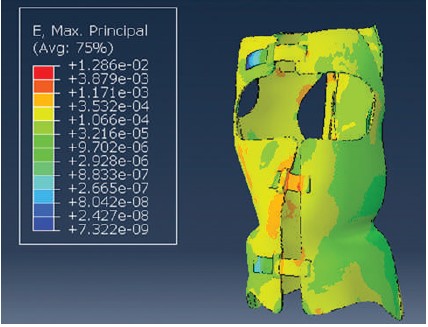
Figure 9: Strain on the polymer brace Nylon 66-30% carbon
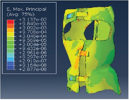
Figure 10: Strain on the polymer brace Nylon 66-50% Mica
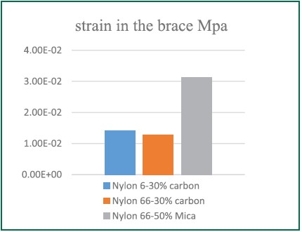
Figure 11: Maximum comparison chart of created strain in the brace
3.3. Displacement Survey
According to the review we conducted, the rate of strain in Nylon 66 with 30% carbon has the least strain and Nylon 66 with 50% Mica has the highest strain. After reviewing the stress and strain on the brace in three different materials, we examined the amount of displacement in the same three materials, as shown in Figures 12, 13, and 14. Comparison chart of maximum created displacement on the brace in three different materials is as follows in Figure 15.
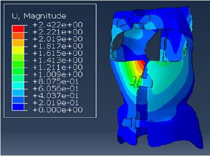
Figure 12: Displacement on the polymer brace 60-30% carbon
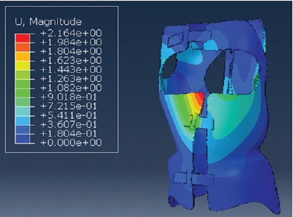
Figure 13: Displacement on the polymer brace Nylon 66-30% carbon
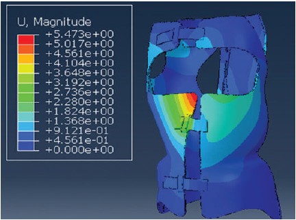
Figure 14: Displacement on the polymer brace Nylon 66-50% Mica
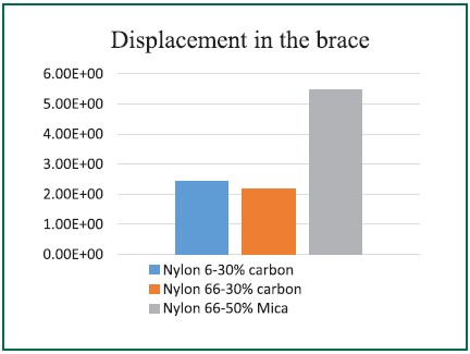
Figure 15: Comparison chart of maximum created displacement on the brace
Once we created displacement on the brace, we found that Nylon 66 with 50% Mica has the highest rate of displacement and Nylon 66 with 30% carbon has the lowest.
In this study we reviewed the stress, strain and displacement in braces. It is important to measure stress and strain on the patients’ bodies, because when the stress and strain goes up to a certain degree, it can deform the body and ultimately fail as a brace, which may cause major health problems.
The main reason for the choice of analytical software in this study (instead of using mathematical formulas or doing laboratory work), is because simulation can be used as a means to measure quantities that would otherwise be very costly and, in some cases, impossible to measure. Furthermore, there is a higher degree of accuracy in software analysis than in laboratory and mathematical work, and by reducing the amount of errors in the process we can provide a more accurate answer.
This redesigned brace was compared with other braces made up to now, and in addition to the treatment of scoliosis, it can also be used to treat Lordosis and Kyphosis, due to its design, which makes this brace different from other braces.
According to the surveys conducted on three different materials we concluded that a brace made of Nylon 66 with 50% Mica performs better than two other materials examined of Nylon 66 with 30% carbon. This is because the rate of stress is lower after loading as well as the rate of strain and displacement, and this material shows more flexibility in the brace.
The authors would like to thank the Trauma Research Center and the research team at Baqiyatallah University.